
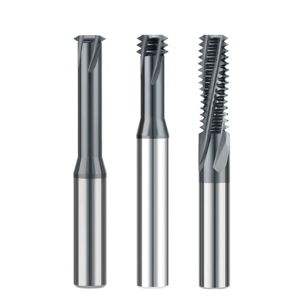
Last month, we received several broken tools and two 4140 quenched-and-tempered steel test blocks from an Ohio precision client. Their production supervisor was at his wits’ end. While threading high-value hydraulic valve blocks, they had ditched taps to avoid broken tools in blind holes. They switched to thread end mills for steel to eliminate tap breakage, but new issues emerged: pitch diameters were out of tolerance, the “Go” gauge jammed after two turns, and tool tips suffered micro-chipping by the third hole.
When we ran tests in our shop, the CAM program revealed the root cause. To achieve smoother cutting, the programmer had defaulted to conventional milling for the circular interpolation path.
Over fifteen years of manufacturing tools and supporting US and European shops, we have seen this exact scenario countless times. Machinists know the rules of climb milling vs conventional milling for external contours. But once a tool enters a deep steel hole, choosing the right method often becomes a blind spot.
This oversight is costly when machining alloy steels, mold steels, or hardened materials (HRC 45–55). Thread milling is not just a scaled-down version of planar side milling. Tight hole spaces easily trap chips, causing re-cutting and jamming. During 3-axis helical interpolation, the entry direction controls chip thickness, heat distribution, and tool deflection.
Choosing the wrong direction leads to initial slippage and rubbing during conventional milling. This creates surface work hardening and amplifies tool deflection, destroying expensive workparts. Have you ever faced this on the shop floor? Your machine is rigid, coolant pressure is high, and parameters match the manual. Yet, your threads still fail gauge tests, and tool life plummets.
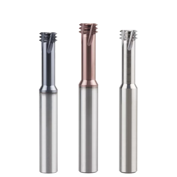
On-Site Comparative Testing: Cutting Force Performance of Climb Milling vs Conventional Milling on Steel Using Thread End Mills
Many machinists assume conventional milling cushions the cut and protects the machine spindle. However, over a decade of troubleshooting out-of-spec threads in production shops proves the opposite. When running dedicated thread end mills for steel on small-diameter internal threads, the severe wrap angle along the hole wall completely rewrites standard side-milling force dynamics.
Piezoelectric dynamometer tests show that internal conventional milling generates 1.5 to 2 times the radial push-off force of climb milling. This force deflects the tool toward the bore centerline, causing pitch diameter taper and flank angle distortion. Climb cutting does produce a higher initial impact, but its resultant force vectors press back into the cut path. That inward force stabilizes the tool and locks in true thread geometry.
From Maximum Chip Thickness to Zero: How Climb Milling Prevents Friction-Induced Work Hardening on the Workpiece Surface
During a process audit on 4140 Q&T steel (HRC 32–36) for a drivetrain manufacturer, we placed thermal sensors inside blind holes to evaluate cutting heat. Climb milling hits the steel at maximum chip thickness and tapers out to zero. Because the chip has sufficient cross-sectional bulk at shear entry, over 75% of the cutting heat leaves with the evacuated chip, sparing the hole wall from thermal soak.
This thick-to-thin chip dynamic is critical when machining heat-sensitive alloy steels. The cutting edge exits cleanly under zero mechanical load without secondary rubbing. This clean exit prevents the formation of an abrasive, work-hardened white layer on the thread flanks. Our test logs confirm that this heat-flushing mechanism delays thermal fatigue micro-cracks on your threadmill by hundreds of holes while keeping surface finishes clean.
The Actual Impact of “Extrusion-Sliding” During the Entry Phase of Conventional Milling on Micro-Chipping of Solid Carbide Threadmill Edges
Failed tools returned to our lab show consistent damage patterns: heavy rake face micro-chipping and localized coating spalling. Under 500x magnification, you rarely find even flank wear bands. Instead, the cutting edges show severe mechanical fatigue from extreme cyclic rubbing. In conventional milling, the tooth starts at zero chip thickness; before reaching the shear threshold, the honed micro-edge rubs and burnishes against the steel for dozens of microns.
This initial rub-and-burnish effect is devastating on chrome-moly alloys. It work-hardens the surface ahead of the cut, forcing each tooth to hammer through a harder crust under intense tangential friction. For a rigid solid carbide threadmill, this repetitive side-loading exceeds the transverse rupture strength of the carbide substrate. If your threads show ragged crests or material tearing, this initial rubbing phase is almost certainly the root cause.
Principles for Matching Climb Milling Entry Impact with Machine Spindle/Ballscrew Backlash
Climb milling is not an automatic fix for every machine tool on the floor. When visiting shops running machining centers with high service hours, we often hear complaints of chatter marks or gouging after switching to climb toolpaths. The cutting force vectors pull the tool along the feed vector. If your machine’s ballscrews have more than 0.015 mm of lash, the tool will grab that play and jump forward, triggering severe chatter.
We advise against running aggressive climb feed rates on machines with poor dynamic rigidity. Before starting a long production run, indicate your table while jogging the axis against a stop to check actual preload. You can also program a 50% feed deceleration along the lead-in arc. If machine wear cannot be adjusted out immediately, falling back to conventional milling at a 30% reduced feed can stabilize the cut and save your thread end mill from chipping.
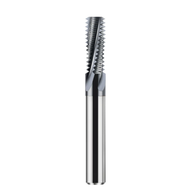
Blind and Deep Hole Cutting: Real Pain Points in Chip Control and Evacuation during Thread Milling
In deep-hole threading, steel chips trapped inside a confined bore act like a guillotine for the cutting tool. When thread depth reaches 2D or 3D, coolant forms stagnant eddies at the bottom of the bore. This forces sharp spiral chips back into the active cutting flutes instead of clearing them away. For precision machine shops, the key to successful deep hole thread milling is not pushing cutting speed, but establishing a clear escape path for chips.
Tool breakage in deep bores rarely stems from natural flank wear; it occurs when chips pack tightly inside the flutes, causing sudden torque spikes. Confined internal spaces distort chip exit angles, turning loose debris into abrasive particles that gouge new thread crests. Re-engineering your toolpath and coolant flow delivers far better process reliability than constantly tweaking spindle RPM.
Blind Hole Climb Milling (Bottom-Up): The Fundamental Principle for Preventing Secondary Chip Cutting at the Hole Bottom
Traditional top-down helical passes often cause catastrophic edge chipping because gravity drags heavy chips directly into the cutting zone. At an automotive tooling plant in Stuttgart, we solved chronic edge failures by reversing this sequence completely. By plunging the cutter to the bottom clearance of the pilot hole first, the tool executes thread milling while feeding upward toward the hole opening.
This bottom-up climb milling strategy uses cutter momentum and upward fluid flow to eject hot chips through the open bore above. Chips never settle in front of the active cutting teeth, completely eliminating chip packing and tool binding. In a production run of over 400 blind holes, this strategy raised our Go/No-Go thread gauge pass rate to a flawless 100%.
Climb-Milling vs. Conventional Milling for Through-Holes: A Specialized Technique to Suppress Lateral Vibration in Long-Overhang, Thin-Walled Steel Components
Standard machining rules must always adapt to structural workpiece rigidity. When threading a 6mm thin-walled alloy sleeve with a 3.5D tool overhang, standard climb milling caused severe radial chatter. The intermittent impact loads flexed the thin wall, generating loud screeching and fish-scale ripple marks across the pitch diameter.
To stabilize the cut, we switched the program to conventional (up) milling. In up-milling, the cutting tooth transitions from thin to thick chip load, creating continuous reverse tension that pulls the flexible tool firmly against the bore wall. This dampens harmonic resonance, trading minor tool flank wear to preserve component roundness and ensure chatter-free thread flanks.
Chip Evacuation Performance and Internal Coolant Pressure: How High-Pressure Coolant Multiplies Thread Cutting End Mill Life
Without adequate kinetic energy behind your coolant, even premium geometries fail inside deep holes. In our shop tests on 316L stainless steel, standard 30-bar external coolant allowed stringy chips to bird-nest around the neck of the tool. This poor evacuation led to erratic surface finishes and premature edge wear across the middle thread teeth.
Upgrading to 70-bar high-pressure through-spindle coolant completely transformed the cut. The focused fluid jet reached the flute stagnation point, blasting chips out of the bore within a split second of shear formation. This prevented built-up edge (BUE) and extended the working life of our solid carbide thread mills while yielding mirror-like pitch diameters.
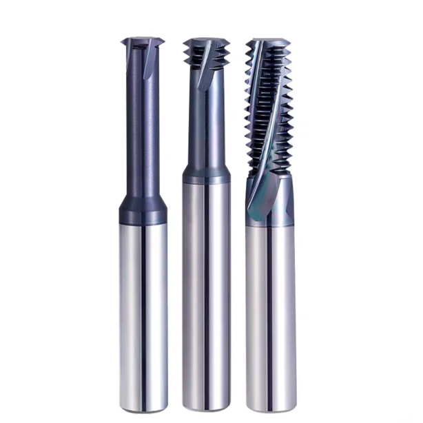
Practical Machining of Hardened Mold Steel: Optimizing Limits for HRC55 Carbide Thread End Mills
Machining pre-hardened mold blocks leaves zero margin for programming error. When tapping or threading inserts at HRC 48–55, a broken tool scraps an expensive finished workpiece. At this hardness, material elongation drops drastically while frictional shear stress surges, making conventional tapping methods completely obsolete.
Success with carbide thread end mills on HRC55 mold steel requires managing micro-level radial loads rather than maximizing metal removal rates. Careful toolpath planning, proportional radial step-overs, and smooth roll-in transitions are essential to prevent thermal micro-cracking and sudden tooth breakage.
Why Climb Milling is Strictly Preferred Over Conventional (Up) Milling for Hardened Mold Steels (e.g., D2/H13) at HRC 48–55
On an H13 die block hardened to HRC 52, conventional (up) milling destroyed a tool in just four holes. In up-milling, the cutting edge rubs and burnishes the work surface before shearing begins. This compressive friction creates a work-hardened white layer over 10 microns deep, driving local hardness past HRC 60 and spalling the carbide substrate instantly.
Climb milling is mandatory when working with steels harder than HRC 48. By entering the cut at maximum chip thickness, the tool shears clean metal immediately, avoiding catastrophic rubbing and frictional work-hardening. This sharp cutting action maximizes the edge toughness of specialized carbide thread end mills in hard-part machining.
Radial Depth Allocation for Multi-pass Climb Milling: Engineering Parameters to Eliminate Thread Taper
Slender cutters often push off against hardened steel, resulting in tapered threads that fit loosely at the top but bind tightly at the bottom. Splitting the thread depth into equal 50/50 cuts still overloads the tool on the second pass. To guarantee straight walls, we use a three-pass radial step-down macro that balances cutting pressure.
Our proven depth-of-cut distribution assigns 65% of the thread profile to the roughing pass and 35% to the semi-finishing pass, capped by a final zero-offset spring pass. This diminishing load strategy offsets tool deflection and holds pitch diameter tolerances within 0.008 mm across deep holes, ensuring smooth gauge entry every time.
Combining Roll-in Arc Entry with Climb Milling: Technical Details on Eliminating Entry-Point Marks
Hardened steel is extremely sensitive to entry impact shocks. Linear or 90-degree perpendicular plunge entries create localized pressure spikes that leave microscopic witness marks on the thread wall. These indentations act as stress-concentration points in high-pressure molds and cause No-Go gauges to bind falsely during inspection.
To eliminate dwell marks, always program a 180-degree tangential roll-in arc from the center of the bore. This circular lead-in allows cutting forces to ramp up smoothly to full radial engagement without shock loading the flutes. This smooth transition protects the tool’s relief angles from micro-chipping and delivers clean, seamless thread flanks during thread milling.
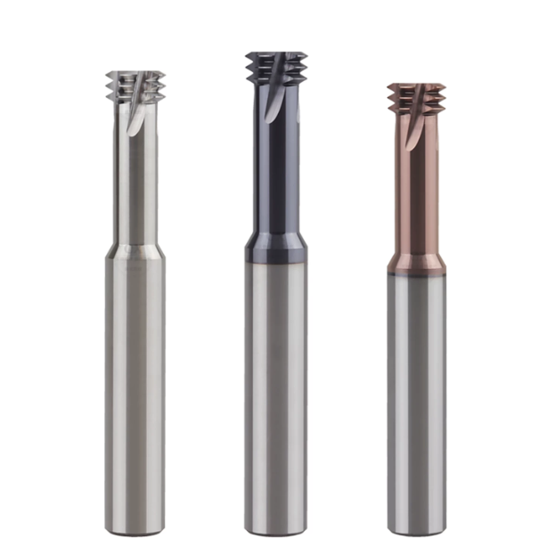
Machine Tool Feed Rate Correction: Why Controller Interpolation Speed Can Be Misleading
A common technical support call involves shops snapping tools on the very first helical pass despite following catalog speeds. The issue usually traces back to how the CNC interprets programmed feed rates during circular motion. Operators often assume the programmed F-value represents the cutting edge speed along the hole wall. However, internal arc interpolation on 3-axis machines alters the actual path geometry significantly.
In straight-line cuts, the tool center and the outer cutting edge travel at identical linear velocities. Inside a confined bore, the tool center traces a much tighter radius than the outer contour. Without automatic controller compensation or programmed feed correction, the tool teeth experience extreme overload. Understanding this kinematic reality is essential to prevent edge chipping during deep-hole thread milling.
The Linear Velocity Trap in Arc Interpolation: Calculating Tool Center Feed vs. Edge Feed
We often see this issue when shops cut threads in tough alloy steels like AISI 4340. For example, milling an M12×1.5 thread with a 9.5mm cutter using an uncorrected edge feed rate will fracture the tool within half a turn. The closer the cutter diameter is to the hole diameter, the shorter the distance traveled by the tool center relative to the bore wall.
To keep edge load within safe limits, calculate the center feed rate(F center) using the ratio (D hole – D tool) / D hole * F contour. For that M12 thread, the reduction factor is roughly 0.21, meaning the center feed must run at just 21% of the perimeter rate. Applying this conversion protects high-performance thread end mills from instant torque overloads.
Axial Feed Differences in Climb vs. Conventional Milling: Tuning Controller Dynamics for Pitch Accuracy
When threading deep holes, parts can pass pitch diameter checks but fail thread ring gauge tests due to subtle cumulative lead errors. This discrepancy is rarely caused by ballscrew thermal growth; instead, servo lag is usually the culprit. In helical climb milling, the Z-axis feeds downward at a constant rate while the X and Y axes switch acceleration profiles sinusoidally at high frequencies.
Climb milling creates pulsing cutting forces, while conventional milling generates continuous drag. To prevent lead error across quadrant transitions, enable advanced look-ahead functions like Fanuc AICC II (G08 P1) or calibrate Siemens CYCLE832 tolerances. Matching servo dynamics to cutting forces ensures exact helical tracking when running a precision thread end mill in steel components.
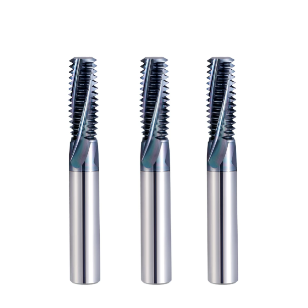
Reducing Cost Per Hole: Customization Advice and Benchmarks from SAMHO Thread End Mill Supplier
In high-volume steel production, calculating tooling costs solely by catalog purchase price is a costly mistake. True machining costs must account for machine downtime, tool change frequency, gauge inspection labor, and part scrap risks. Successful internal threading relies on systematic stability across the entire process chain rather than saving a few dollars on initial tooling.
At SAMHO, we measure true tool performance through wear consistency and tool life cycle productivity. Before upgrading a production line, evaluate real shop-floor metrics such as workholding rigidity, machine dynamics, and scrap rates. Sustainable cost reduction happens when process reliability eliminates unexpected line stoppages and scrap during thread milling.
Stringent Toolholder Runout Standards: Maintaining TIR Within 0.003mm
No matter how accurate the cutter geometry, poor toolholder concentricity destroys performance. In climb milling, cutting teeth engage the metal at maximum chip thickness. If Total Indicated Runout (TIR) at the tool tip exceeds 0.003mm, a single protruding tooth absorbs all initial impact loads while other teeth barely cut.
Repeated clamping in standard ER collets often degrades concentricity past 0.008mm, causing premature and erratic carbide edge failure. Switching to high-precision hydraulic chucks or shrink-fit holders guarantees dynamic runout below 0.003mm. Maintaining this level of concentricity ensures every flute of your thread end mill shares the chip load evenly.
Rapid On-Site Wear Assessment: Timing Tool Changes to Protect 2B/3B Thread Tolerances
Waiting for a thread gauge to fail before replacing a cutter risks scrapping entire production batches. In critical aerospace or fluid-power components requiring Class 2B or 3B fits, worn tools rapidly push pitch diameters out of spec. Experienced machinists listen for shifts from a clean cutting hum to a dull, metallic grind, signaling flank wear exceeding 0.1mm.
Inspect cutting edges with a pocket magnifier for peeled coatings, exposed carbide substrate, or micro-welded steel on the rake face. For hardened materials, program hole-count tool-life limits directly into your machine macros. Retiring a carbide thread end mill before severe wear takes hold avoids costly thread extrusion and out-of-round bores.
Cost Analysis for Batch Machining Steel Parts: Factoring in Tool Breakage and Scrap Rates
Cost calculations must account for the value accumulated in a workpiece prior to the threading operation. Consider a massive hydraulic valve block that has already undergone hours of multi-axis machining. If a cheap, low-toughness cutter snaps inside a deep blind hole, EDM extraction and weld repairs quickly wipe out any minor tooling savings.
For high-volume steel programs, tooling costs should always be weighed against the part’s overall first-pass yield. Premium solid carbide tools provide predictable tool wear, eliminating unexpected catastrophic failures. When tackling challenging steel specifications or tight pitch tolerances, optimizing parameters with an experienced thread end mill supplier ensures maximum profitability.






