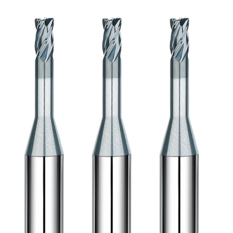
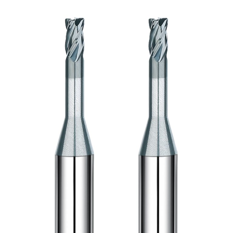
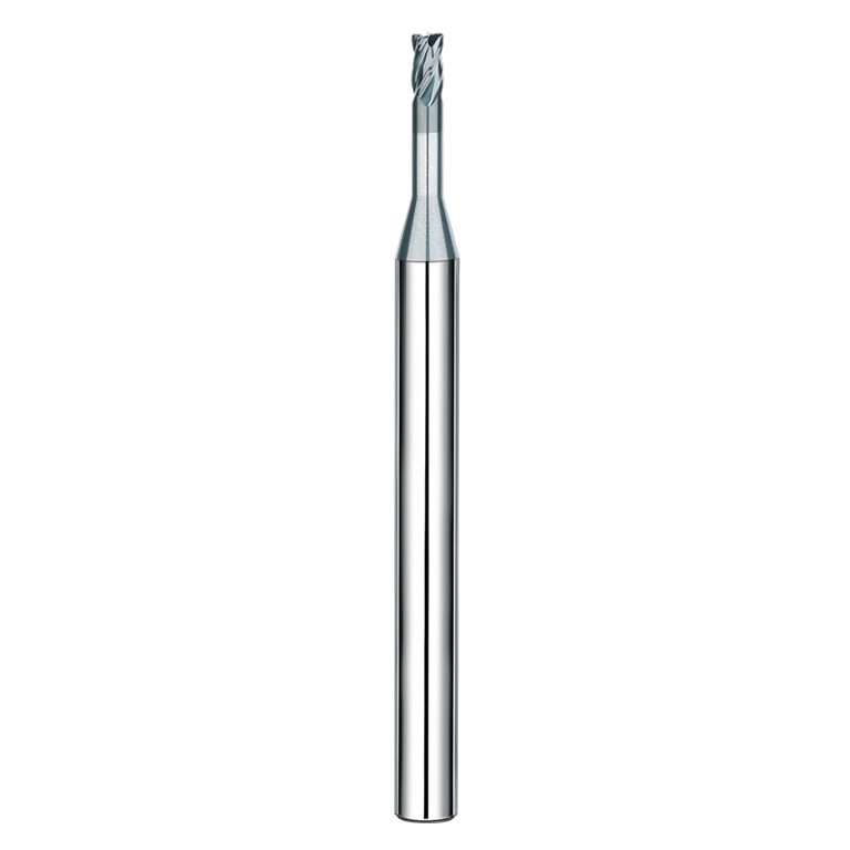
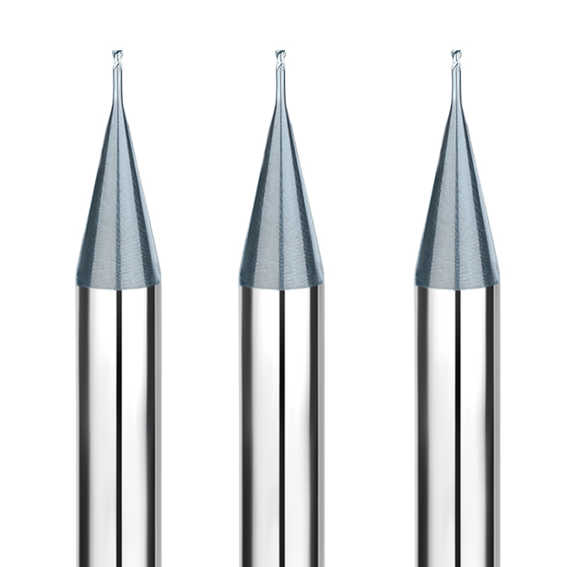
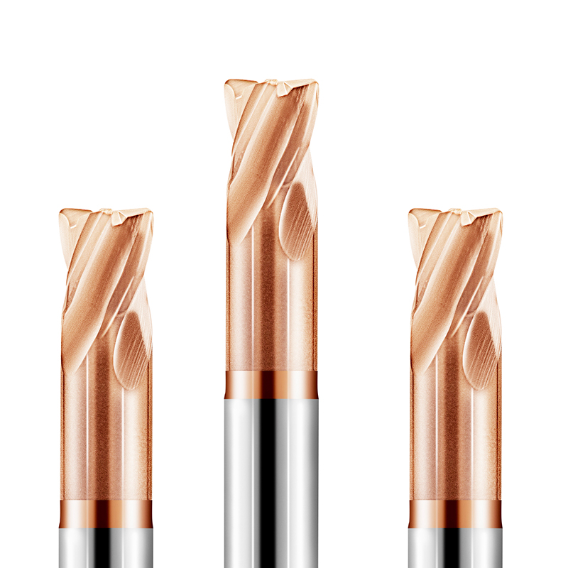
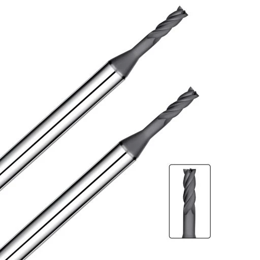
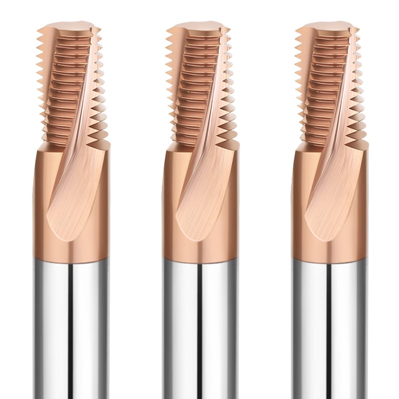
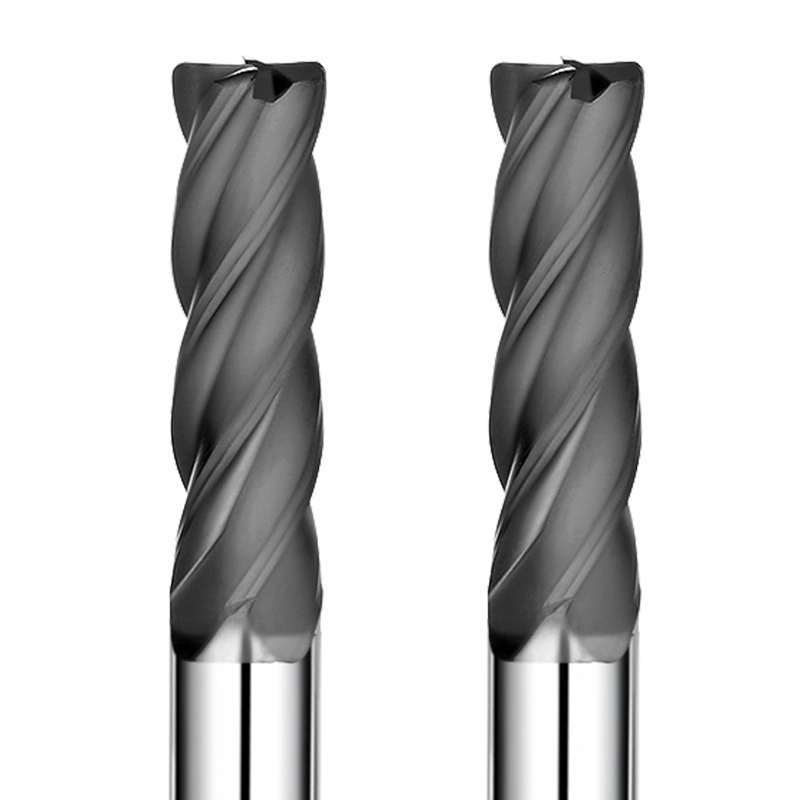
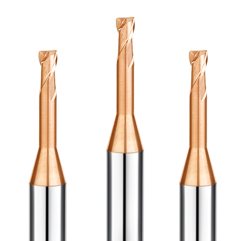
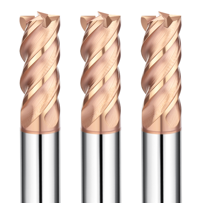
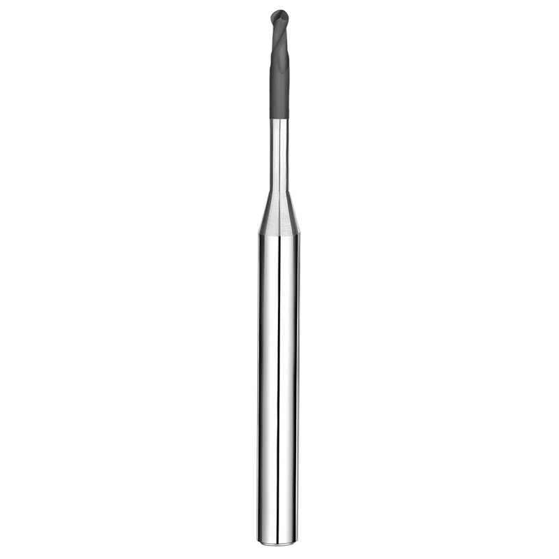
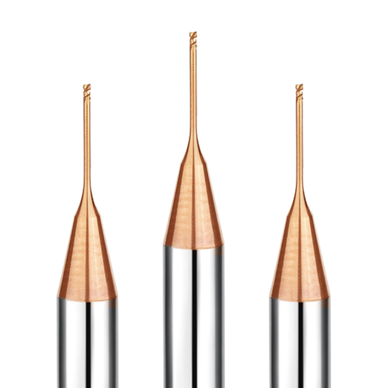
In tungsten-copper machining, tools must meet exceptionally high standards. They require not only precise cutting performance but also excellent wear resistance and long-term stability. The SAMHO 4-flute long neck rounded end mill (available in sizes D12R0.05 to D3R0.5 mm) is engineered to meet these demands. It delivers high-precision, consistent machining while ensuring superior surface finish and extended tool life. This end mill is ideal for CNC applications involving tungsten-copper materials, helping manufacturers achieve efficient and reliable results.
Advanced Technical Features
High-Adhesion Coating for Ultra-Long Tool Life
Our proprietary coating technology gives the cutting tools exceptional hardness and chemical stability.
- Wear Resistance: Maintains a sharp edge even during prolonged, continuous machining of tungsten-copper alloys.
- Micro-Chipping Prevention: Keeps the coating firmly bonded to the carbide substrate under high-speed, high-friction conditions.
Corner Radius Geometry for Machining Complex Shapes
The precision-engineered corner radius ensures excellent performance when machining internal corners, transition zones, and complex cavities in tungsten-copper parts.
- High-Precision Surfaces: Delivers smooth and uniform surface finishes on tungsten-copper workpieces.
- Mold and High-Precision Part Machining: Provides stable results without micro-cracks.
High-Efficiency 4-Flute Design for Cool Cutting
The sharp 4-flute geometry reduces cutting heat and improves chip evacuation.
- Maximized Chip Evacuation: Quickly clears tungsten-copper chips from the cutting area.
- Reduced Cutting Load: Minimizes heat buildup and prevents cracking in brittle materials.
Ultra-Fine Grain Carbide Substrate with Precision Grinding
Made from high-strength, ultra-fine grain carbide and CNC-ground specifically for tungsten-copper machining, this tool delivers consistent repeatability and precision.
- Strict Dimensional Tolerance: Ensures stable and consistent batch production of parts.
- Enhanced Fracture Resistance: Extends tool life, ideal for highly abrasive tungsten-copper materials.
Target Applications & Industries
This series of tungsten-copper-specific 4-flute long-neck rounded end mills is engineered for CNC applications and is widely suitable for:
- Precision Machining of Tungsten-Copper Parts: Achieves high-precision surfaces and consistent dimensions for functional and structural components.
- Complex Cavities and Internal Corners: Ideal for machining transition areas, deep cavities, and intricate internal features.
- Highly Abrasive Tungsten-Copper Materials: Maintains tool life and performance even when cutting high-hardness, wear-prone materials.
- High-Precision Contours and Complex Structures: Meets the demands of precision molds and intricate part geometries.
Why Source Wholesale from SAMHO?
- High-Precision Manufacturing: Engineered for CNC machining, with shank diameter tolerances strictly controlled within 0–0.005 mm. This ensures excellent clamping stability and consistent machining results.
- Superior Wear Resistance: A specialized coating combined with a high-strength carbide substrate extends tool life and maintains cutting performance on highly abrasive tungsten-copper alloys.
- Adaptable to Complex Parts: The precision corner-radius tip easily handles internal corners, transition zones, and intricate mold cavities, delivering consistent surface quality.
- Flexible Customization: Supports OEM/ODM, providing tailored solutions to meet specific customer requirements.
- Reliable Partner: SAMHO ensures stable supply and strict quality control, helping manufacturers achieve efficient and repeatable production.
Recommended Materials for Machining (Highly Recommended: ⭐️ | Recommended: ⭕️ | Suggested: ◯)
| DIE STEEL |
Grade |
| Carbon steels (S45C/S55C) |
|
| Alloy steels (SK/SCM/SUS) |
|
| Prehardened steels (NAK/HPM) |
|
| Hardened steels (~55/~60/~70HRC) |
|
| SPECIAL MATERIAL |
| Aluminum alloys |
|
| Graphite |
|
| Copper |
|
| Plastics |
|
| Tungsten copper |
⭐ |
| Carbon fiber |
|
| Titanium alloys |
|
| Heat resistant alloys |
|
| Cemented carbide |
|
| Hard brittle (non-metallic) material |
|
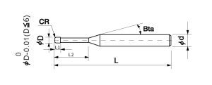
Total 51 models
| Model Number |
Outside Diameter |
Length of Cut |
Effective Length |
Corner Radius |
Shank Taper Angle |
Overall Length |
Number of Flutes |
Shank Diameter |
In Stock |
| CGLSR4-010005040 |
1 |
2 |
4 |
0.05 |
15° |
50 |
4 |
4 |
○ |
| CGLSR4-010005060 |
1 |
2 |
6 |
0.05 |
15° |
50 |
4 |
4 |
○ |
| CGLSR4-010005080 |
1 |
2 |
8 |
0.05 |
15° |
50 |
4 |
4 |
○ |
| CGLSR4-010005100 |
1 |
2 |
10 |
0.05 |
15° |
50 |
4 |
4 |
○ |
| CGLSR4-01001040 |
1 |
2 |
4 |
0.1 |
15° |
50 |
4 |
4 |
○ |
| CGLSR4-01001060 |
1 |
2 |
6 |
0.1 |
15° |
50 |
4 |
4 |
○ |
| CGLSR4-01001080 |
1 |
2 |
8 |
0.1 |
15° |
50 |
4 |
4 |
○ |
| CGLSR4-01001100 |
1 |
2 |
10 |
0.1 |
15° |
50 |
4 |
4 |
○ |
| CGLSR4-01501060 |
1.5 |
3 |
6 |
0.1 |
15° |
50 |
4 |
4 |
○ |
| CGLSR4-01501080 |
1.5 |
3 |
8 |
0.1 |
15° |
50 |
4 |
4 |
○ |
| CGLSR4-01501100 |
1.5 |
3 |
10 |
0.1 |
15° |
50 |
4 |
4 |
○ |
| CGLSR4-01501120 |
1.5 |
3 |
12 |
0.1 |
15° |
50 |
4 |
4 |
○ |
| CGLSR4-01501160 |
1.5 |
3 |
16 |
0.1 |
15° |
50 |
4 |
4 |
○ |
| CGLSR4-01502060 |
1.5 |
3 |
6 |
0.2 |
15° |
50 |
4 |
4 |
○ |
| CGLSR4-01502080 |
1.5 |
3 |
8 |
0.2 |
15° |
50 |
4 |
4 |
○ |
| CGLSR4-01502100 |
1.5 |
3 |
10 |
0.2 |
15° |
50 |
4 |
4 |
○ |
| CGLSR4-01502120 |
1.5 |
3 |
12 |
0.2 |
15° |
50 |
4 |
4 |
○ |
| CGLSR4-01502160 |
1.5 |
3 |
16 |
0.2 |
15° |
50 |
4 |
4 |
○ |
| CGLSR4-02001060 |
2 |
4 |
6 |
0.1 |
15° |
50 |
4 |
4 |
○ |
| CGLSR4-02001080 |
2 |
4 |
8 |
0.1 |
15° |
50 |
4 |
4 |
○ |
| CGLSR4-02001100 |
2 |
4 |
10 |
0.1 |
15° |
50 |
4 |
4 |
○ |
| CGLSR4-02001120 |
2 |
4 |
12 |
0.1 |
15° |
50 |
4 |
4 |
○ |
| CGLSR4-02001160 |
2 |
4 |
16 |
0.1 |
15° |
50 |
4 |
4 |
○ |
| CGLSR4-02001200 |
2 |
4 |
20 |
0.1 |
15° |
50 |
4 |
4 |
○ |
| CGLSR4-02002060 |
2 |
4 |
6 |
0.2 |
15° |
50 |
4 |
4 |
○ |
| CGLSR4-02002080 |
2 |
4 |
8 |
0.2 |
15° |
50 |
4 |
4 |
○ |
| CGLSR4-02002100 |
2 |
4 |
10 |
0.2 |
15° |
50 |
4 |
4 |
○ |
| CGLSR4-02002120 |
2 |
4 |
12 |
0.2 |
15° |
50 |
4 |
4 |
○ |
| CGLSR4-02002160 |
2 |
4 |
16 |
0.2 |
15° |
50 |
4 |
4 |
○ |
| CGLSR4-02002200 |
2 |
4 |
20 |
0.2 |
15° |
50 |
4 |
4 |
○ |
| CGLSR4-02005060 |
2 |
4 |
6 |
0.5 |
15° |
50 |
4 |
4 |
○ |
| CGLSR4-02005080 |
2 |
4 |
8 |
0.5 |
15° |
50 |
4 |
4 |
○ |
| CGLSR4-02005100 |
2 |
4 |
10 |
0.5 |
15° |
50 |
4 |
4 |
○ |
| CGLSR4-02005120 |
2 |
4 |
12 |
0.5 |
15° |
50 |
4 |
4 |
○ |
| CGLSR4-02005160 |
2 |
4 |
16 |
0.5 |
15° |
50 |
4 |
4 |
○ |
| CGLSR4-02005200 |
2 |
4 |
20 |
0.5 |
15° |
50 |
4 |
4 |
○ |
| CGLSR4-0301120 |
3 |
6 |
12 |
0.1 |
15° |
50 |
4 |
4 |
○ |
| CGLSR4-0301160 |
3 |
6 |
16 |
0.1 |
15° |
50 |
4 |
4 |
○ |
| CGLSR4-0301200 |
3 |
6 |
20 |
0.1 |
15° |
50 |
4 |
4 |
○ |
| CGLSR4-0301250 |
3 |
6 |
25 |
0.1 |
15° |
60 |
4 |
4 |
○ |
| CGLSR4-0301300 |
3 |
6 |
30 |
0.1 |
15° |
75 |
4 |
4 |
○ |
| CGLSR4-0302120 |
3 |
6 |
12 |
0.2 |
15° |
50 |
4 |
4 |
○ |
| CGLSR4-0302160 |
3 |
6 |
16 |
0.2 |
15° |
50 |
4 |
4 |
○ |
| CGLSR4-0302200 |
3 |
6 |
20 |
0.2 |
15° |
50 |
4 |
4 |
○ |
| CGLSR4-0302250 |
3 |
6 |
25 |
0.2 |
15° |
60 |
4 |
4 |
○ |
| CGLSR4-0302300 |
3 |
6 |
30 |
0.2 |
15° |
75 |
4 |
4 |
○ |
| CGLSR4-0305120 |
3 |
6 |
12 |
0.5 |
15° |
50 |
4 |
4 |
○ |
| CGLSR4-0305160 |
3 |
6 |
16 |
0.5 |
15° |
50 |
4 |
4 |
○ |
| CGLSR4-0305200 |
3 |
6 |
20 |
0.5 |
15° |
50 |
4 |
4 |
○ |
| CGLSR4-0305250 |
3 |
6 |
25 |
0.5 |
15° |
60 |
4 |
4 |
○ |
| CGLSR4-0305300 |
3 |
6 |
30 |
0.5 |
15° |
75 |
4 |
4 |
○ |
Contour Milling Parameters
| Work Material |
Tungsten Copper |
| (mm) Diameter |
(mm) Effective Length |
(min-1) Speed |
(mm/min) Feed |
| D1 |
4 |
12000 |
800 |
| D1 |
6 |
10000 |
600 |
| D1 |
8 |
8500 |
400 |
| D1 |
10 |
7500 |
300 |
| D1 |
4 |
12000 |
800 |
| D1 |
6 |
10000 |
600 |
| D1 |
8 |
8500 |
400 |
| D1 |
10 |
7500 |
300 |
| D1.5 |
6 |
10000 |
1200 |
| D1.5 |
8 |
8500 |
800 |
| D1.5 |
10 |
7500 |
500 |
| D1.5 |
12 |
7000 |
300 |
| D1.5 |
16 |
6000 |
300 |
| D1.5 |
6 |
10000 |
1200 |
| D1.5 |
8 |
8500 |
800 |
| D1.5 |
10 |
7500 |
500 |
| D1.5 |
12 |
7000 |
300 |
| D1.5 |
16 |
6000 |
300 |
| D2.0 |
6 |
12000 |
1500 |
| D2.0 |
8 |
10000 |
1100 |
| D2.0 |
10 |
9000 |
1000 |
| D2.0 |
12 |
8500 |
800 |
| D2.0 |
16 |
7000 |
600 |
| D2.0 |
20 |
7000 |
400 |
| D2.0 |
6 |
12000 |
1500 |
| D2.0 |
8 |
10000 |
1100 |
| D2.0 |
10 |
9000 |
1000 |
| D2.0 |
12 |
8500 |
800 |
| D2.0 |
16 |
7000 |
600 |
| D2.0 |
20 |
7000 |
400 |
| D2.0 |
6 |
12000 |
1500 |
| D2.0 |
8 |
10000 |
1100 |
| D2.0 |
10 |
9000 |
1000 |
| D2.0 |
12 |
8500 |
800 |
| D2.0 |
16 |
7000 |
600 |
| D2.0 |
20 |
7000 |
400 |
| D3.0 |
12 |
10000 |
1800 |
| D3.0 |
16 |
8500 |
1400 |
| D3.0 |
20 |
8000 |
1200 |
| D3.0 |
25 |
7000 |
800 |
| D3.0 |
30 |
6000 |
500 |
| D3.0 |
12 |
10000 |
1800 |
| D3.0 |
16 |
8500 |
1400 |
| D3.0 |
20 |
8000 |
1200 |
| D3.0 |
25 |
7000 |
800 |
| D3.0 |
30 |
6000 |
500 |
| D3.0 |
12 |
10000 |
1800 |
| D3.0 |
16 |
8500 |
1400 |
| D3.0 |
20 |
8000 |
1200 |
| D3.0 |
25 |
7000 |
800 |
| D3.0 |
30 |
6000 |
500 |
Note:
*Decrease both spindle speed and feed rate proportionally when the milling parameters exceed the machine’s maximum
spindlespeed;
*Recommend using a non-contact measuring device to avoid damaging the precision tip point.