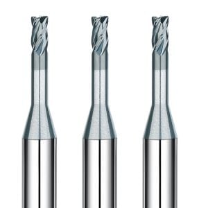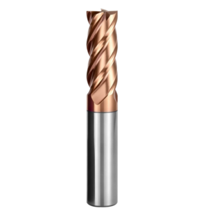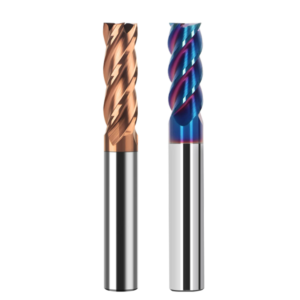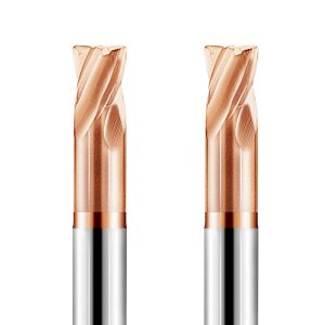
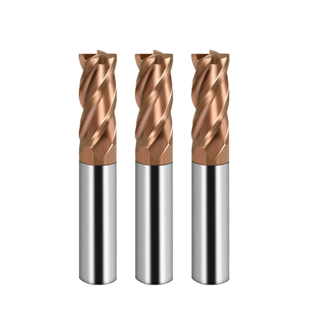
A Tier 1 supplier making automotive injection molds sent several fractured 6-flute carbide end mills to our testing lab. The tool tips were chipped, the coatings had flaked off, and the workpiece walls showed heavy chatter marks. The customer’s process supervisor asked: “Why can’t these tools survive 20 minutes in HRC65 powder-metallurgy die steel?”
We see this exact failure pattern dozens of times every year. The cutters featured ultra-fine sub-micron carbide substrates, AlTiSiN nano-composite coatings, and total runout under 3 microns. Yet the CAM code revealed the real culprit: the programmer used conventional parameters and set radial stepover above 10% of the tool diameter.
At HRC65, hardened steel exhibits virtually zero plastic ductility, and shear-zone temperatures quickly exceed 1000°C. If the radial engagement end mill parameter exceeds critical limits, the contact arc expands instantly. Heat cannot escape into the micro-chips, forcing thermal energy back into the carbide matrix and causing immediate thermal shock and macro-chipping.
Over 16 years of tooling manufacturing and on-site support, we have proven one consistent rule: machining ultra-hard steels requires limiting the end mill radial cut to a strict micro-window. When you pair shallow stepover with correct feed compensation for chip thinning, cutting forces transform into clean shearing action instead of destructive crushing.
Given that everyone has access to premium machine platforms and coated solid-carbide tools, why do some setups run smoothly for hours while yours shatters the moment it enters a corner?
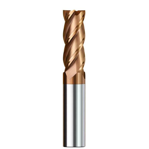
Why Radial Engagement Is the Critical Threshold for Tool Life When Machining HRC65 Hardened Steel
When you put a hardness tester on HRC65 steel, you know the material has lost its plastic elongation. We can grind sub-micron grain substrates and apply heat-resistant nano-coatings to boost tool life. But inside the cut, the tool faces extreme mechanical shock and intense heat pulses. If edge contact lasts even slightly too long, shear stress concentrates right on the edge radius, destroying the coating in milliseconds.
In customer workshops, we remind programmers that the radial engagement end mill setting is not just a CAM input value. It controls the thermal equilibrium of the entire cut. Exceed the safe contact arc, and friction heat cannot escape through the chips. The cutting edge anneals and fails immediately. Keep the contact angle narrow, and the flute gets clean air-cooling on every rotation to extend tool life.
Field Case Study: Catastrophic Chipping of End Mills When Radial Engagement Exceeds 8% of Tool Diameter
We once troubleshot a stamping die shop machining Cr12MoV cavities hardened to HRC64–65. Rushing to hit a deadline, the operator programmed a 10mm carbide tool with a 1.2mm stepover, reaching 12% radial engagement. Within two minutes, the spindle load spiked with an ear-piercing scream. Under our shop microscope, all primary flutes were blown out, with carbide shards welded to the cavity wall.
The shop foreman initially blamed our tool’s transverse rupture strength. We pulled the CNC controller log and proved the real issue. Past HRC62, if an end mill radial cut exceeds 8% of the tool diameter, normal entry impact shocks exceed the carbide’s fracture toughness limit. We dropped the stepover to 0.4mm (4% radial cut) with an adaptive toolpath. The identical batch of tools then ran 4.5 hours of uninterrupted pocket milling without a single chipped tooth.
The Role of Radial Engagement in Managing Heat Accumulation Zones During Trochoidal and Dynamic Milling of HRC 65 Steel
Many programmers apply soft-steel trochoidal toolpaths to hard die steels without checking the heat transfer zone. Milling HRC65 is pure thermodynamics: cutting heat either leaves inside the chip or drives into the tool and workpiece. If your toolpath lacks corner radius smoothing, radial engagement spikes in corners. That sudden heat burst creates thermal stress cracks across the cutting edge within milliseconds.
In our multi-axis cutting tests, managing HRC65 end mill radial engagement creates a stable thermal cycle. Flutes enter and exit the thin shear zone rapidly. During the out-of-cut phase, shop air blasts cool the tool face. This intermittent cut converts continuous thermal soak into high-frequency, low-amplitude pulses. It stops micro-cracks from spreading down carbide grain boundaries and lets modern coatings do their job.
A Common Misconception When Troubleshooting Chatter: The Non-Linear Relationship Between Radial Depth of Cut and Feed per Tooth
When chatter marks appear, operators instinctively turn down the feed override knob. In light radial cuts on hardened steel, reducing feed is the fastest way to ruin a cutter. When radial depth of cut drops, the chip-thinning effect becomes extreme. If you do not compensate with higher feed per tooth, the cutting edge cannot bite into the stock. Instead, it burnishes and rubs across work-hardened steel under heavy pressure.
That is why end mill radial depth of cut and feed per tooth have an inverse, non-linear relationship. When radial engagement drops to 2%–4%, feed per tooth must often jump by 30% to 80%. This keeps the true chip thickness larger than the hone radius on the cutting edge. Keep your radial stepover narrow, run a firm feed to force a clean chip shear, and surface chatter marks disappear.
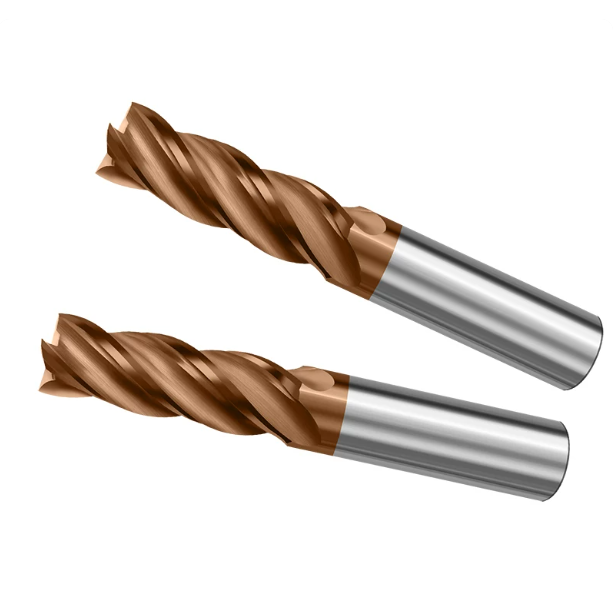
Our Recommended Parameters and Engagement Strategies for Milling HRC65 Steel
Running standard mold steel parameters on HRC65 hardened steel will trigger heavy chatter within seconds. Our shop floor tests prove there is no generic speed-and-feed recipe for ultra-hard metals. Success depends on dynamic balance: machine tool rigidity, toolholder runout below 0.003mm, and workpiece grain microstructure. We bypass wide contact arcs entirely. Instead, we pair ultra-shallow radial width with deep axial engagement to eliminate deflection spikes.
When dialing in HRC65 steel milling parameters, engineers must shift focus from gross material removal rate to flute cycle loading. Pinning radial engagement down to a micro-window slashes bending moments on the carbide core. It also unlocks room for chip-thinning feed compensation. Keeping contact arcs narrow preserves machine tool rigidity against severe cut resistance.
High Cutting Speed (Vc) Combined with Minimal Radial Depth of Cut: Effectively Removing Heat via Chips
Watch an optimized high-speed center cutting HRC65 die steel: chips fly off in purple-blue ribbons while the cavity stays cool to the touch. Severe plastic deformation in hard milling generates immediate, intense friction heat. Traditional heavy roughing at low RPM traps this heat within the cutting zone. That thermal energy rapidly soaks into the carbide substrate, causing coating delamination and thermal shock fractures.
We solve this thermal bottleneck by clamping the end mill radial depth of cut to a micro-range (0.15mm–0.40mm) while driving cutting speeds to 120–180 m/min. Shallow cuts restrict flute engagement duration to mere milliseconds. The heat never penetrates the tool substrate or the workpiece; it stays locked inside the chip. Blasting the cut with cold compressed air evacuates these glowing chips instantly.
Chip Evacuation and Hardened Layer Penetration in Shallow Cuts: Preventing End Mill Slippage and Rubbing
In light-stepover hard milling, the primary threat is not edge breakage, but flute burnishing against the strain-hardened skin. HRC65 steels work-harden violently during shearing, creating a microscopic outer layer exceeding HRC67. If the next tooth passes through this zone without biting beneath it, the cutter rubs against the glaze. This friction generates extreme heat, destroying the cutting edge within minutes.
To prevent destructive rubbing, we program climb milling exclusively so the endmill bit enters the cut at maximum chip thickness. This forces the edge to shear through the work-hardened crust cleanly. We also ban liquid flood coolant, running cold-air blasts with MQL instead. Recutting a single hardened chip trapped in the cavity will micro-chip the flute and ruin a high-polish surface finish.
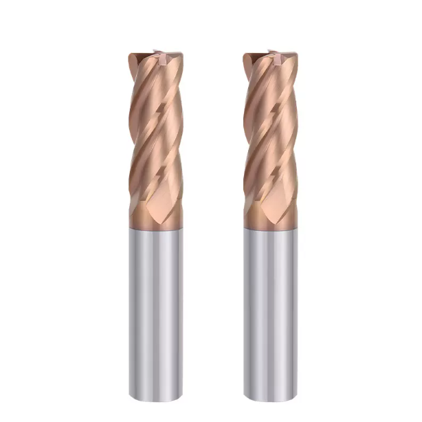
Micro-Geometric Design: Balancing Radial Rake Angles and Edge Honing for Structural Rigidity
Clamping an HRC65 block into a machining center magnifies every tool grind imperfection. In our grinding shop, five-axis CNC wheel dressers are held to sub-micron standards for hardened steel geometry. Positive rake angles designed for aluminum or pre-hardened steels fracture instantly against high-hardness substrates. The objective is not low cutting resistance, but channeling intense shear forces safely into the tool core.
Under these extreme loads, tailoring the radial rake angle end mill geometry means sacrificing sharpness for macro-rigidity. A heavy negative rake angle provides massive material backing for the edge. Yet, without precision micro-chamfers and relief clearance, cutting pressure spikes and overheats the spindle. Balancing edge strength and material shearing flow is what separates premium hard-milling cutters from general-purpose tooling.
Our Experience with HRC65 Materials: Why End Mills Require a Slightly Negative Radial Rake Angle (-12° to -15°)
Years ago, we ground custom cutters for a German shop machining cold-work die inserts at HRC64+. Our prototype flutes ran conservative negative rakes of -6° to -8°. In five-axis cut tests, flutes chipped within three minutes from tensile stress fatigue. HRC65 tool steels have zero yield capacity. Insufficient negative rakes expose the carbide crystal boundary to fatal tensile loads.
Extensive dynamometer testing showed the ideal radial rake angle end mill geometry sits between -12° and -15°. This negative profile redirects normal cutting forces into compressive stresses directed toward the tool centerline. Tungsten carbide features exceptional compressive yield strength, easily absorbing these loads. The tool resists micro-fractures from abrasive carbides, even during high-feed, shallow cuts.
Resisting Impacts from a Hardened Matrix: The Role of Honing Radius and Core Thickness in Radial Cut Stability
Many programmers believe razor-sharp cutting edges produce superior surface finishes, but raw unhoned flutes reveal micro-serrations under the microscope. In shallow cuts, a microscopic notch will initiate rapid crack propagation the moment it strikes hardened martensite. We process every finished cutter through drag finishing or micro-blasting to establish a flawless edge hone.
During an ultra-light radial cut, we hold the edge hone between 8μm and 12μm, backed by a web core measuring 65% to 70% of tool diameter. If the hone radius is too large, thin chips cannot clear the rounding, causing tool burnishing and push-off. If the core web is too thin, the shank flexes under dynamic impact. Pairing a dialed-in hone radius with a rigid core eliminates edge flutter entirely.
Addressing Chip Evacuation and Harmonic Resonance: Variable Helix Geometry Under Low Radial Engagement
A piercing high-frequency screech at the machine spindle rarely means the cutter is blunt. It indicates the equal pitch of standard flutes is exciting the natural harmonic resonance of the spindle setup. In light-stepover milling, force pulses hit the workpiece at identical intervals. These rhythmic strikes trigger destructive harmonic chatter on thin walls and cavities, peeling high-end coatings off the tool.
We resolve this harmonic spike by grinding flutes with differential indexing and variable helix angles, such as 35°/38° or 41°/43°. This asymmetrical geometry breaks the impact rhythm, scattering cutting frequencies across the radial engagement end mill contact zone. Although flute volume is slightly reduced, it remains ideal for fine hardened steel chips, while the reinforced cross-section maximizes torsional stiffness.
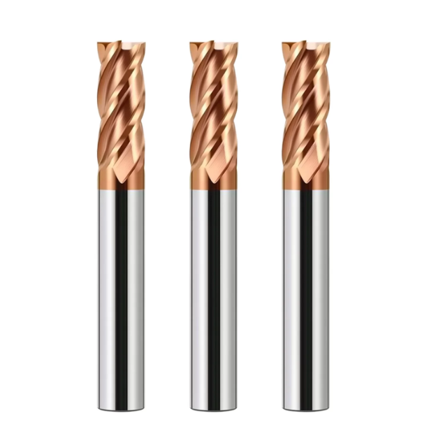
Controlling Tool Tips and Overhangs: Using Corner Radius End Mills to Mitigate Localized Cutting Stress Concentrations
Failure analysis across dozens of die-mold shops shows that over 70% of premature failures start within two millimeters of the corner. On HRC65 steel, a square end mill’s 90-degree corner functions as an isolated stress trap. With zero adjacent carbide to support the tip, cutting heat and normal forces spike instantly. Even minor mechanical shocks trigger immediate micro-chipping along the carbide grain boundaries.
Whenever part geometry permits, we advise machine shops to replace square tooling with a corner radius end mill. Swapping a sharp corner for an arc redistributes stress concentrations into a broad load-bearing profile. It also packs solid carbide directly behind the transition point. This extra support buffers the tip against severe shock loads, keeping dynamic milling cuts stable under high mechanical pressure.
Moving Beyond Sharp, 90-Degree Edges: The Impact Resistance of Corner Radius End Mills vs Square End Mills in Shallow-Width Machining
While optimizing hardened insert milling for a medical moldmaker, we found the shop insisted on using square tools for shallow profiling. Flutes chipped at the outer corners after only 30 minutes in the cut. Under our shop microscope, we showed the team that flat corners act like micro-punches. Each entry cycle hammers the corner, shearing the coating and snapping the carbide tip.
We resolved the issue by switching the shop to a rohová fréza s rádiusem using an R0.5 or R1.0 profile. The arc smooths tool engagement into a sweeping surface pass rather than a blunt line strike. Cutting forces resolve cleanly into combined radial and axial vectors. More carbide mass behind the radius improves heat conduction, preventing tip annealing during light-stepover cuts.
5-Axis/Deep-Cavity Milling: Eliminating Chatter in Long-Overhang Applications by Adjusting Radial Depth of Cut
Deep cavity milling with extended tool reach is tough, especially in HRC65 tool steels. In one large stamping die project, tool clearance required a shrink-fit extension running at an extreme 6D overhang. The spindle shrieked immediately upon entry, leaving ugly chatter marks across the workpiece walls. Within half a shift, several premium tools sheared off at the neck from heavy bending fatigue.
Operators often drop feed rates or pick smaller cutters, but our fix is to shrink the end mill radial cut down to 1.5%–2% of cutter diameter. Radial deflection forces decay cubically as stepover narrows, immediately subduing long-overhang chatter. While chip volume per tooth decreases, five-axis machine interpolation allows for faster table feeds, clearing deep cavities without surface vibration.
Analysis of Bull-Nose End Mill Engagement in Arc-Transition Zones: Programming Toolpaths for Constant Effective Radial Engagement
Do not rely solely on nominal stepover values when generating 3D finishing toolpaths in CAM. A bull-nose tool contacts sculptured surfaces differently than a standard straight flute. As curvature shifts, the cutting zone moves dynamically from the side wall to the bottom corner radius. Without trajectory compensation, tool engagement spikes in concave corners and overloads the cutting edge.
We configure CAM post-processors with adaptive arc smoothing so HRC65 end mill radial engagement stays within a fixed contact-angle window. The system adjusts the toolpath ahead of tight internal corners, rolling the radius smoothly through the turn. Keeping the contact arc constant protects the corner radius from sudden gouging, delivering dependable surface finishes across complex hardened contours.
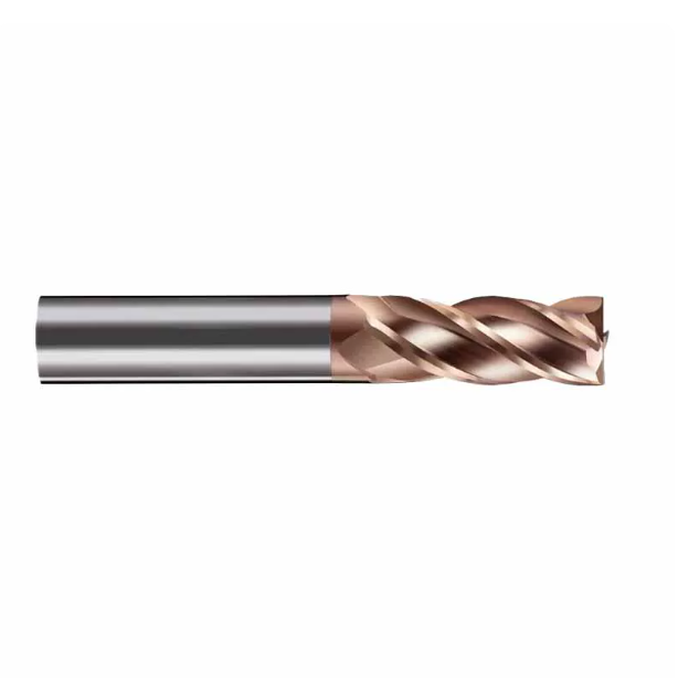
A Field Guide to Troubleshooting Tool Wear: Deducing Flaws in Radial Cutting Parameters from End Mill Wear Patterns
In our testing lab, we inspect worn cutters under high-depth-of-field microscopes to interpret edge wear scars. Every micro-chip, flaked coating patch, and heat burn records what happened inside the cut. When a tool fails prematurely, dropping spindle speed or swapping brands rarely helps. The best fix is reverse-engineering your parameters from the physical wear pattern on the flutes.
We track end mill tool wear signatures to correct radial engagement and toolpath flaws. On HRC65 material, incorrect stepover leaves telltale marks on cutting edges. Excessive radial engagement causes thermal fractures and edge breakdown. Running cuts too shallow with low feed results in abrasive flank wear. Reading these wear signs lets you optimize cutting parameters for real shop floor conditions.
Notch Wear or Thermal Cracking? Determining Whether End Mill Wear Is Caused by Excessive Radial Engagement
When inspecting a worn cutter, look closely at the flank face for comb-like transverse cracks or notched grooves along the depth-of-cut line. Micro-cracks running perpendicular to the edge signal thermal fatigue from cyclic shock. Deep, localized notches at the cut line indicate severe abrasive wear against the work-hardened shell of the part.
Evaluating end mill tool wear confirms whether you exceeded safe radial cut limits. If thermal micro-cracks appear under the lens, flute contact time is too long, trapping excessive heat in the tool. Cut your radial engagement by 30% to 50% and raise surface speed to clear heat in the chips. If you see notch wear, check CAM corners for sudden radial engagement spikes.
Diagnosing Entry Impact in Climb vs Conventional Milling: Addressing Initial Micro-Chipping at Shallow Radial Depths of Cut
Forces on the cutting edge differ fundamentally between climb and conventional milling during light radial passes. Machining cold-work die steels above HRC62 often produces tiny edge micro-chips within the first few passes. This usually means the machine is conventional milling, where the flute rubs against hard stock at zero chip thickness before cutting, tearing the edge.
Aligning your end mill radial depth of cut with the right entry vector resolves initial chipping. If your cutters suffer premature edge fractures, switch to climb milling so teeth engage at maximum chip thickness for clean shearing. If workpiece geometry forces you to up-mill, raise nominal feed per tooth to skip the rubbing zone and protect the cutting edge.
Practical Implementation: Fine-Tuning the Cutting Width for HRC65-Hardened Materials Based on Machine Rigidity and Spindle Runout
Theoretical parameters mean little if your machine tool lacks dynamic rigidity. Values proven on high-end lab equipment perform differently on aging shop floor centers. Tooth shock loads multiply when spindle runout increases from 0.003mm to 0.015mm. In HRC65 materials, runout variations spike the radial load on a single flute, triggering early edge fatigue.
Adjust your HRC65 end mill cutting width to match actual spindle runout and machine rigidity. If you run a rigid BT40 or HSK spindle with shrink-fit holders under 3 microns runout, set stepover to 3%–5% of tool diameter for high efficiency. If you run standard collets or older machines, drop stepover to 1.5%–2.5% and raise spindle speed to recover removal rates.
Consistent tool life in HRC65 hardened steel requires syncing tool micro-geometry with radial engagement and spindle dynamics. If you face surface chatter, poor tool life, or corner-clearing issues on powder steels or hardened inserts, we can help. Share your part drawings, material heat-treat specs, and NC code, and we will help you map out the ideal parameters for your setup.